The Importance of Accurate Airflow and Torque Modeling
Modern engine management systems rely heavily on accurate airflow and torque modeling. The airflow influences far more than engine fueling alone, affecting idle control, transmission behavior, stability systems, and the way the vehicle responds to driver demand.
Because of this, errors in airflow or injector data can have consequences well beyond air-fuel ratio. The ECU continuously cross-checks torque against other parameters, such as airflow, to confirm that the engine is operating as expected. When those relationships are inaccurate, the result can be poor drivability, unstable idle, incorrect torque reporting, and transmission behavior that no longer matches the engine’s real output.
Airflow is calculated using a straightforward relationship between air, fuel, and injector data. If we command an air-fuel ratio of 14.7:1 and achieve 14.7:1 at the tailpipe, then the airflow calculation is correct, provided the injector data and fuel pressure are also correct. This is why incorrect injector data can turn a straightforward tune into a major problem. At 14.7:1, there are 14.7 parts air to 1 part fuel. In mass terms, that means 14.7 grams of air for every 1 gram of fuel. The ECU uses injector data to determine how many grams of fuel are delivered for a given pulse width. If that data is wrong, the foundation of the entire tune is wrong.
For example, imagine we believe an injector is 800cc when it is actually 1000cc. When we adjust the VE or MAF to achieve the correct AFR at the tailpipe, or to reduce LTFT and STFT, the airflow being measured or calculated from the MAF, VE, VVE, or Neural Network will be wrong by the same amount. To achieve the correct mixture, we would need to reduce the VE, MAF, VVE, or NN by 20% because the injector is delivering 20% more fuel than the data suggests. That may correct the mixture, but it also causes the airflow calculation to be 20% lower than the real airflow.
This creates several tuning problems. Across almost all calibrations, two constants remain: idle control and torque output. Idle is controlled by airflow, either directly or through a torque calculation, and that torque calculation ultimately depends on airflow and ignition timing. If the airflow model is wrong, idle tuning will also be wrong. Torque output is equally important. Because many modern vehicles share platforms and components, such as ZF transmissions used across multiple brands, the torque value reported to the transmission must be accurate for correct line pressure and shift torque reduction. In the example above, if airflow is undercalculated by 20%, torque will also be undercalculated by a similar amount. The transmission may then feel less precise and may flare during shifts. Some late-model transmissions can adapt enough to partly mask the problem, but the underlying error remains and can increase the risk of premature failure. This is one reason tuning chips can create drivability and transmission issues when they do not maintain an accurate torque calculation.
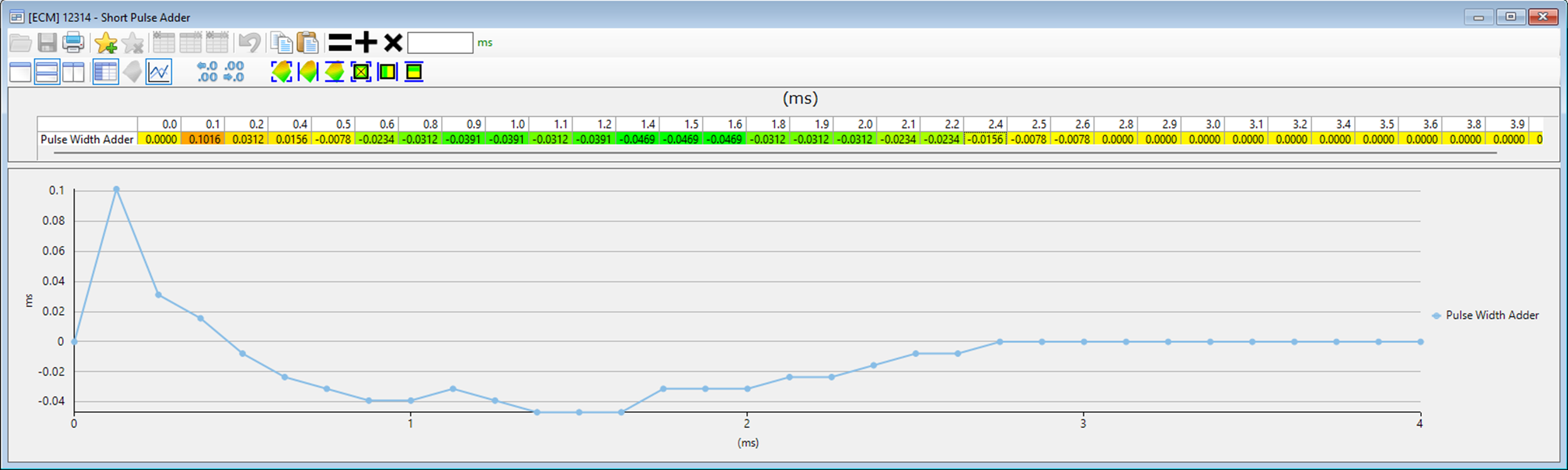
In some cases, the error is large enough to be obvious because the calculated airflow will not match what would normally be expected for a known combination of parts. In other cases, the issue is less obvious but just as important, especially at low pulse widths with larger injectors. A stock injector might idle at 2-3ms, while a larger injector at idle or light load may operate as low as 0.5ms and can be limited by minimum pulse width. At very low pulse widths, an injector may no longer behave linearly. In other words, adding more pulse width does not always result in a proportional increase in fuel delivery. Depending on the injector, this non-linear behavior can begin somewhere below 4ms. Different manufacturers address this in different ways: GM uses a short pulse adder, Jeep/Ram uses a pulse-width-versus-mass table, and Ford uses separate high and low flow rates split at a specific fuel mass where behavior changes from linear to non-linear.
The example below shows GM short pulse correction. At very low flow rates, the commanded injector pulse may be too short to reliably overcome spring pressure and open the injector enough to deliver the required fuel mass. In other cases, the injector may stay open too long because the spring cannot close it quickly enough. The table below adjusts injector pulse based on flow testing so the ECU can deliver accurate fuel mass at flow rates below the injector’s linear range. Below a certain pulse width, the injector can no longer deliver fuel consistently. That point is the minimum pulse width.
What does this mean for tuning?
1. Choose quality injectors with reliable flow data that suits the vehicle you are tuning.
2. Choose injectors with a minimum pulse width low enough to suit the engine.
3. Tune the airflow model (MAF/VE/VVE/NN) before finalizing idle, so any idle adjustments are based on correct airflow data.